Support Documents
This is a short list of what you will need to accomplish the task of building a basic sector file for the POSCON Radar Client.
- Source of information (AIP or any equivalent): you will need the coordinates of all airspace sectors, airports, runway thresholds etc...).
- Coordinates converter: a service that allows you to convert your coordinates to the SCT format (it is planned to build a tool internally for POSCON users -not high priority currently-, if you know any service that does this, you can use it).
- A text editor: Notepad++ or VSCode recommended.
Format
The following are standard formats used in SCT and SCT2 files.
-
Comments: you can add comments that are ignored by the client by using a semicolon followed by your comment.
Example:; This is a comment ; The following section is a danger area called OJP9 OJP9/H5 N032.17.56.123 E036.49.59.173 N032.29.56.136 E037.10.59.200 DangerZone ; This is also a comment OJP9/H5 N032.29.56.136 E037.10.59.200 N031.43.56.101 E037.39.59.246 DangerZone OJP9/H5 N031.43.56.101 E037.39.59.246 N031.33.56.089 E037.12.59.210 DangerZone OJP9/H5 N031.33.56.089 E037.12.59.210 N032.17.56.123 E036.49.59.173 DangerZone
-
Coordinates: the format used is a 14-character representation of DMS format in a pair of Longitude followed by Latitude, as follows:
- N/E/S/W
- 3-digit degrees
- 2-digit minutes
- 2-digit seconds
-
3-digit decimal seconds
Example:N031.43.26.860 E035.59.40.639 S023.37.33.370 W046.39.33.245
In this document, they will be labeled COORD COORD, the first being Latitude and second Longitude.
-
Colors: RGB with a decimal twist as follows: (BLUE x 65536) + (GREEN x 256) + RED
In order to make it easier to manage colors, you are able to define your colors at the top of the file as follows:#define Runway 986895 #define Coastline 16711680 #define Buildings 5263440
Later in the file, you can use the name of the color as follows:
N028.33.28.946 E032.55.13.806 N028.33.28.981 E032.55.14.932 Coastline
N028.33.28.981 E032.55.14.932 N028.33.25.815 E032.55.18.105 Coastline
N028.33.25.815 E032.55.18.105 N028.33.25.815 E032.55.26.550 Coastline
N028.33.25.815 E032.55.26.550 N028.33.22.643 E032.55.29.723 Coastline
N028.33.22.643 E032.55.29.723 N028.33.22.643 E032.55.39.226 Coastline
-
Display range: Each section is by default displayed at all times. This can be overwhelming if for example fixes are in the hundreds.
To prevent that, the POSCON Radar Client allows users to define a RANGE of zoom that applies to all the items below the declaration.
Format: RANGE [MIN] [MAX]
Where the word RANGE is to be typed literally, [MIN] and [MAX] as numbers representing zoom levels.
Example:[FIXES] RANGE 0 500 CAMRN N040.01.02.290 W073.51.39.808 ...
The above would show all the fixes starting at CAMRN between range levels 0 and 500.
You can define multiple range rules in the same section as follows:[FIXES] RANGE 0 500 AIR28 N040.02.00.700 W081.14.48.091 NUSMM N040.02.01.291 W080.49.02.020 IPURE N040.02.01.870 W074.36.13.798 RANGE 0 0 AZOFE N040.02.16.889 W077.32.55.111 WUGVA N040.02.36.679 W074.50.12.260 JOANE N040.02.38.479 W076.27.21.398 AVUKE N040.02.43.159 W074.12.28.321
Here, the usage of RANGE 0 0 serves as a way to hide the fixes below the declaration.
You can obtain the zoom levels from the POSCON Radar Client marked by RANGE as follows: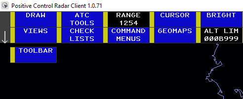
Main Tags
-
[INFO] basic information about the sector as follows:
- Sector Name
- Default/main position
- Default/main airport
- Latitude of center point
- Longitude of center point
- NM per degree of latitude
- NM per degree of longitude
- Magnetic variation
- Scale
-
[AIRPORT] declaration of all airports.
-
Format: ICAO 000.000 COORD COORD.
- ICAO: 4-letter identifier of the airport.
- (000.000) is a placeholder frequency.
-
Format: ICAO 000.000 COORD COORD.
-
[RUNWAY] declaration of all runways.
-
Format: IDENT1 IDENT2 HEADING1 HEADING2 COORD COORD COORD COORD ICAO.
- IDENT1: runway identifier of runway (example: 08R).
- IDENT2: runway identifier of the same runway from the opposite end (example: 26L).
- HEADING1: runway magnetic heading of the IDENT1 end in 3 digits (example: 076).
- HEADING2: runway magnetic heading of the IDENT2 end in 3 digits (example: 256).
- COORD COORD: the first pair is runway threshold coordinates of IDENT1 end.
- COORD COORD: the second pair is the runway threshold coordinates of IDENT2 end.
- ICAO: airport ICAO code identifier (example: OJAI).
-
Format: IDENT1 IDENT2 HEADING1 HEADING2 COORD COORD COORD COORD ICAO.
-
[VOR] declaration of all VOR stations.
-
Format: IDENT FREQ COORD COORD.
- IDENT: the (usually) 3-letter identifier of the VOR station
- FREQ: frequency in MHz with 3 decimal places (###.###).
-
Format: IDENT FREQ COORD COORD.
-
[NDB] declaration of all NDB stations.
-
Format: IDENT FREQ COORD COORD.
- IDENT: the identifier of the NDB station
- FREQ: the frequency in MHz with 3 decimal places (###.###).
-
Format: IDENT FREQ COORD COORD.
-
[FIXES] all waypoints in the sector area.
-
Format: IDENT COORD COORD.
- IDENT: the identifier of the fix.
-
Format: IDENT COORD COORD.
-
[ARTCC HIGH] higher airspace polygons.
-
Format: SECTOR_NAME LINE
- SECTOR_NAME: the name of the sector, could contain spaces.
-
LINE: a pair of coordinates (COORD COORD) x2.
For the purpose of this document, LINE will refer to a pair of coordinates, first is "From Point" and second is "To Point".
Example:KZNY N039.51.00.000 W075.39.00.000 N039.50.06.000 W075.40.12.000
The first pair is (N039.51.00.000 W075.39.00.000) which represents the start point of the line, and the second is (N039.50.06.000 W075.40.12.000) which marks the end point of the line.
Add all the lines forming the sector as needed.
Example:NYO-65 N038.35.05.000 W068.53.00.000 N039.48.30.000 W070.06.20.000 NYO-65 N039.48.30.000 W070.06.20.000 N040.34.36.000 W070.52.46.000 NYO-65 N040.34.36.000 W070.52.46.000 N041.00.00.000 W069.00.00.000 NYO-65 N041.00.00.000 W069.00.00.000 N041.37.00.000 W067.00.00.000
-
Format: SECTOR_NAME LINE
- [ARTCC] + [ARTCC LOW] same as the above section.
-
[LOW AIRWAY] + [HIGH AIRWAY] definition of all airways based on type (low altitude VS high altitude).
-
Format: IDENT LINE
- IDENT: the identifier of the airway. Example: V4)
- POINTS: a collection of either FIXES or coordinates that form the airway line.
-
Example:
V8 GAREN GAREN GRABI GRABI
V8 GRABI GRABI TWERP TWERP
V8 TWERP TWERP FBC FBC
V8 MRB MRB LUCKE LUCKE
V8 LUCKE LUCKE RAYEE RAYEE
V8 RAYEE RAYEE N038.51.34.030 W077.02.11.169
The format is identical to the [ARTCC] sections, where a pair of coordinates are needed to draw a line.
The user has the option of using already defined fixes to replace latitude and longitude values.
Note: when using a fix, you are required to write it twice, first time for latitude value and second for longitude value as shown in the example above: TWERP (LAT) TWERP (LNG) FBC (LAT) FBC (LNG).
-
Format: IDENT LINE
-
[GEO] defines geographical lines with colors. This section can be used to draw line data concerning different parts of the airspace other than the previously defined sections or other geographical landmarks (roads, lakes, airport layouts...).
-
Format: LINE COLOR.
-
LINE: a pair of coordinates (COORD COORD) x2.
-
COLOR: either a decimal value of the color, or a name of a defined color.
Example:N041.37.50.493 W073.52.40.577 N041.37.49.815 W073.52.39.840 RWY N041.37.49.815 W073.52.39.840 N041.37.49.708 W073.52.39.793 RWY N041.37.49.708 W073.52.39.793 N041.37.47.710 W073.52.43.049 RWY N041.37.47.710 W073.52.43.049 N041.37.43.499 W073.52.49.945 RWY N041.37.43.499 W073.52.49.945 N041.37.40.826 W073.52.54.319 RWY N041.37.40.826 W073.52.54.319 N041.37.40.273 W073.52.55.221 RWY
-
-
-
[FREETEXT] any freetext (taxiway labels, stands, airspace MVAs etc...)
-
Format: COORD:COORD:GROUP:TEXT
- COORD:COORD: latitude and longitude of text point.
- GROUP: name of the group that this text belongs to. Example: "KJFK Stand Numbers". Not displayed.
-
TEXT: the actual text that will be displayed.
Example:N031.43.17.859:E036.01.05.060:OJAI Queen Alia Intl.:A N031.43.17.830:E036.00.40.159:OJAI Queen Alia Intl.:A N031.43.31.339:E036.00.21.710:OJAI Queen Alia Intl.:MAINTENANCE APRON N031.43.25.401:E036.00.34.913:OJAI Queen Alia Intl.:JORAMCO ACADEMY N031.43.08.062:E035.59.11.964:OJAI Queen Alia Intl.:S5 N031.43.08.252:E035.59.13.498:OJAI Queen Alia Intl.:S7 N031.43.08.497:E035.59.15.054:OJAI Queen Alia Intl.:S9
-
Format: COORD:COORD:GROUP:TEXT
-
[REGIONS] are polygons which are filled with a color. Mostly used to draw ground layouts of airports.
-
Format: COLOR COORD COORD
The region starts with a color that the region will be filled with, then followed by points (each on a separate line).
The region is ended either by an empty line, or the beginning of a new region, or a new section.
Example:ASDEX_TWAY N040.47.32.250 W073.06.23.453 ; ASDEX_TWAY N040.47.32.374 W073.06.23.033 N040.47.32.479 W073.06.26.195 N040.47.32.109 W073.06.26.199
-
Format: COLOR COORD COORD