Support Documents
Data Blocks (DBs) can be displayed as:
- Full Data Blocks (FDB)
- Limited Data Blocks (LDB)
- Enhanced Limited Data Blocks (E-LDB)
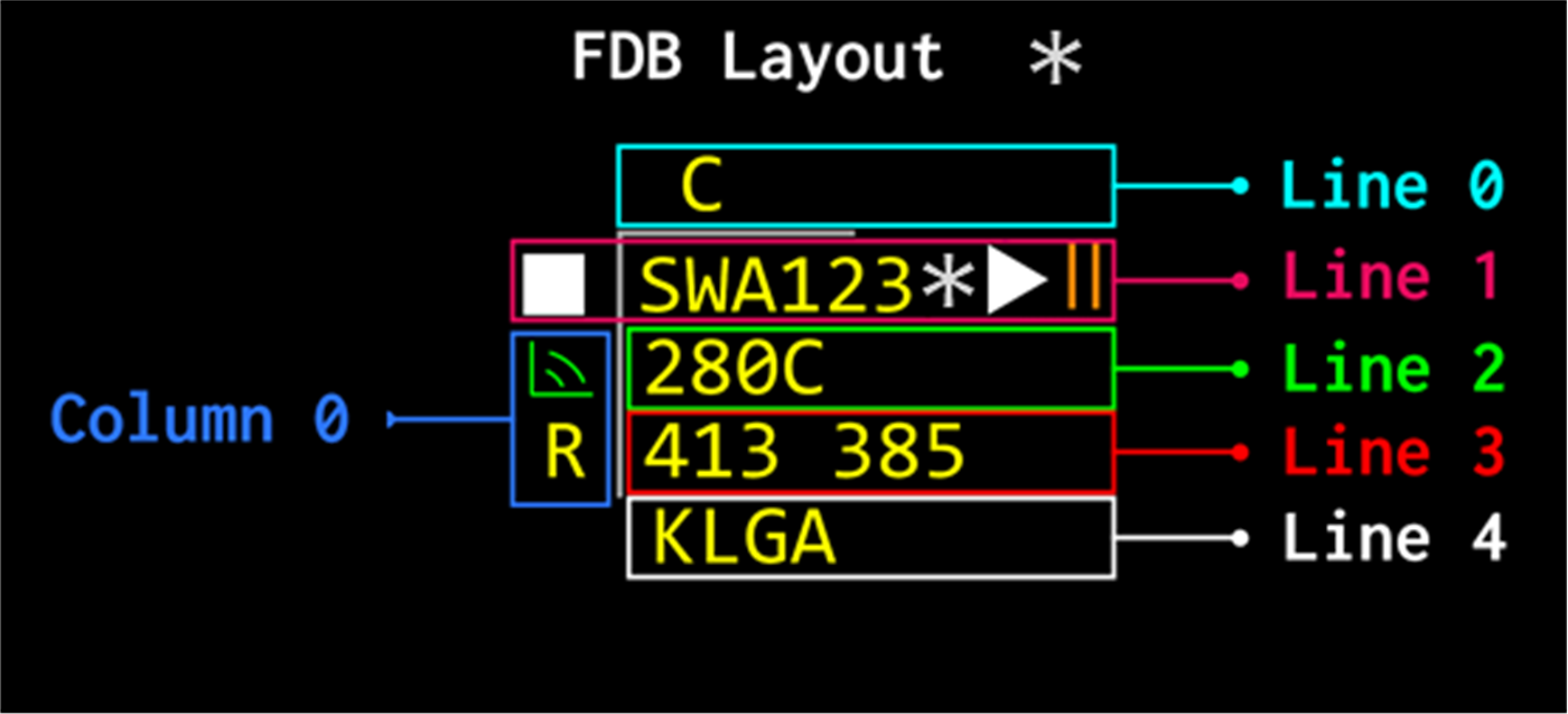
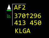
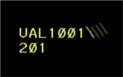
A FDB is the symbology displayed adjacent to a tracked aircraft target on a radar display containing an aircraft position symbol, a leader line, velocity vector line, and the alphanumeric data associated with the aircraft. A FDB is made up of a text array area and a symbology area. The FDB is arranged in 5 lines and 1 column, and the FDB fields (Field A through E) are contained within this structure.
Associated data currently not implemented yet.
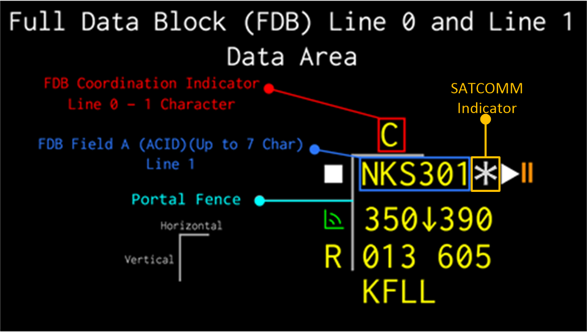
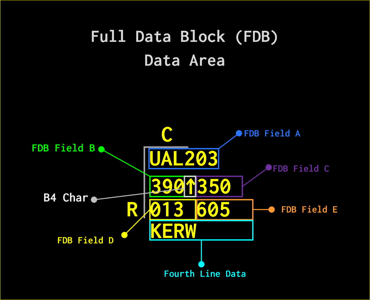
- FDB Field A - ACID (2 to 7 characters). Other data on Line 1 is not implemented yet.
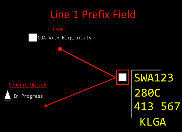
- A Solid square in the CPDLC Indicator Prefix Field shows that the aircraft is connected to the appropriate CPDLC authority and is able to send, receive, and respond to CPDLC Messages.
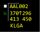
- A Solid upward pointing triangle in the CPDLC Indicator Prefix Field shows that a CPDLC Message has successfully uplinked and is waiting on a response from the Aircraft.
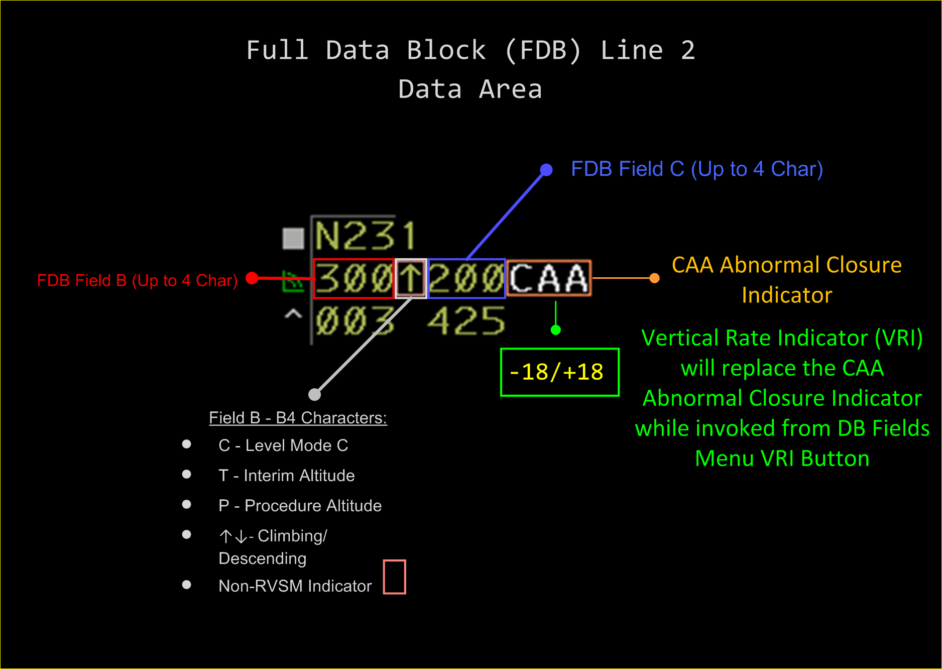
From left to right:
-
FDB Field B, Altitude Field: Altitude in 100s of feet.
- FDB Field B4: Procedural Altitude and Non-RSVM indicator is not implemented yet; the rest of the characters are implemented.
- FDB Field C, Reported Altitude Field: Altitude in 100s of feet.
- Vertical Rate Indicator (VRI): The VRI may be displayed on line 2 to the right of and separated by one space from Field C. The VRI is only displayed when the VRI override state is enabled (button accessed in "DB FIELDS" menu). The CAA is not implemented yet.
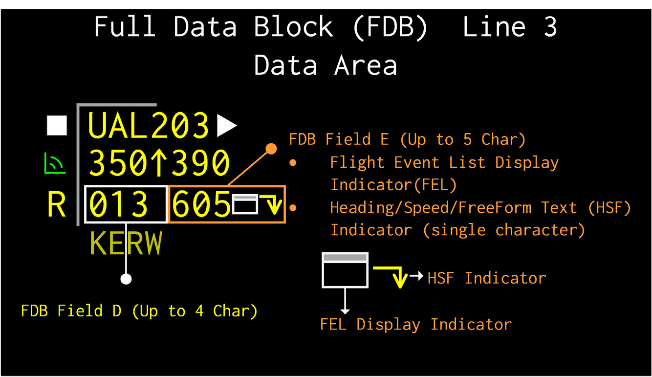
From left to right:
- FD Field D: The Computer Identification Number (CID) of the generated data block.
- FDB Field E: Time shared entries (up to 5 characters) which can include handoff, beacon data, MSAW, interfacility supplemental data, side stream handoff display item, plan data display item, hold and ground speed, or destination (see table below for more info).
- Indicators following Field E - None implemented yet.
Explanations left blank are not implemented yet.
Possible Field E Indicators
EMGR
7700 beacon return - emergency code.
HIJK
7500 beacon return - hijack code.
LLNK
Reserved.
RDOF
7600 beacon return - radio communications failure.
EFC
Reserved.
FAIL
Reserved.
OLD
Reserved.
MIFF
Reserved.
MOFF
Reserved.
MSAW
Reserved.
H-dd
Track is being handed off to sector dd within the center.
HLdd
Track is being handed off intercenter or from an ARTS facility. L will contain the receiving center’s one letter designator, and dd will contain the two-digit ID of the receiving sector.
HLLL
Reserved.
HL
Reserved.
HUNK
Reserved.
HLdL
Reserved.
HLLdL
Reserved.
HLLx
Reserved.
LLdd
Reserved.
O-dd
Handoff has been accepted by sector dd within the center (intracenter), or sector dd has retracted a handoff to an ARTS facility.
OLdd
Handoff has been accepted for an interfacility handoff where L will contain the receiving center’s one letter designator, and dd will contain the two-digit ID of the receiving sector.
OLLL
Reserved.
OUNK
Reserved.
OLLdL
Reserved.
OLdL
Reserved.
OLLx
Reserved.
K-dd
Reserved.
KLdd
Reserved.
KLdL
Reserved.
KLLdL
Reserved.
KLLx
Reserved.
CST
Aircraft is in coast status.
dddd
The beacon code received, if it is different from the assigned code.
NONE
Displayed if the track has an assigned beacon code, and a beacon code is not received.
ddd, CAS: (d)dd, MAS: Mdd
The ground speed (range 001 to 999).
MISM
Reserved.
CODE
Temporarily displays the primary beacon code when an alert condition (e.g., 7700) is causing a special beacon code to be displayed.
FRZN
Displayed when the DB is in frozen (FRZN) status indicating that the DB is unpaired from the target.
SIDE
Reserved.
PLAN
Reserved.
DATA
Reserved.
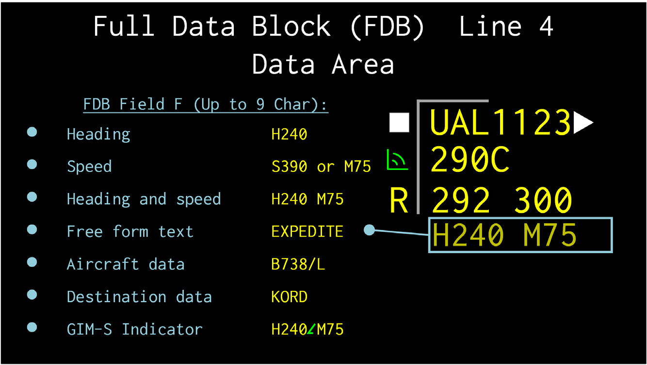
Data displayed on the 4th line and includes heading, speed, heading and speed, free form text, aircraft data, destination data, or GIM-S Speed Indicator.
The only FDB 4th line variables implemented are "aircraft data" and "destination data". These can be accessed by navigating to "DB FIELDS" and clicking on the "TYPE" and "DEST" toggle buttons respectively.
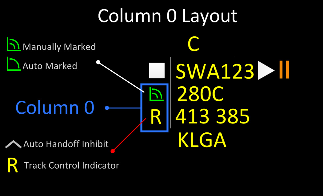
From top to bottom:
- On-Frequency Indicator - not implemented yet.
-
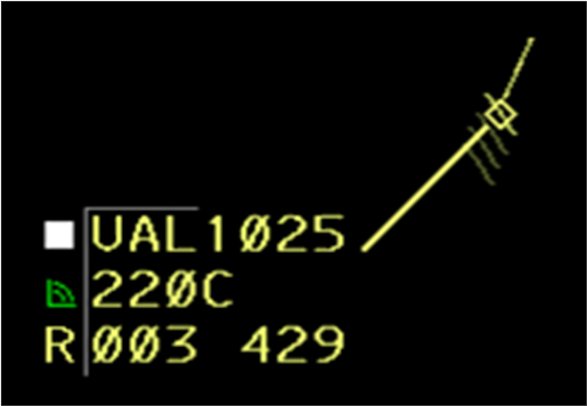
Characters "R" and a "^". The rules for these FDB indicators are as follows:
- The “R” (yellow coding) is displayed if the the sector invoking the FDB does not have track control.
- The “^” (white coding) Auto Handoff Inhibit is not implemented yet.
The controller can offset the position of DBs and adjust leader line length.
To adjust the leader line length for all FDBs, open the Data Block Fields Toolbar:
- TBP the FDB LDR button to decrease leader line length of FDBs.
- TBE the FDB LDR button to increase leader line length of FDBs.
NOTE: The leader line length has a range of 0 to 3.
To adjust the leader line length for individual FDBs:
/ {length 0-3} <SPACE> {FLID} <KBE>
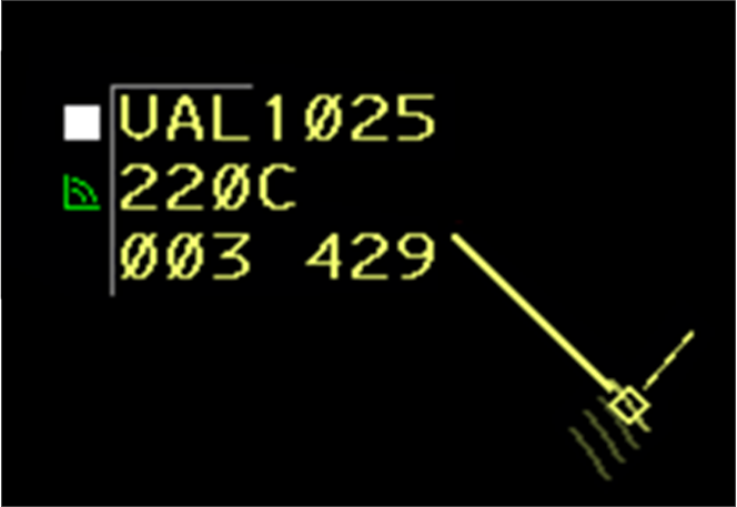
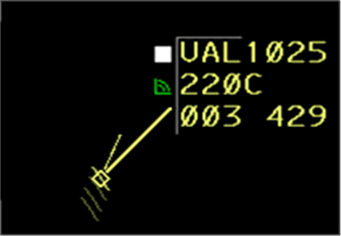
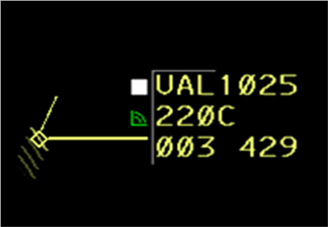
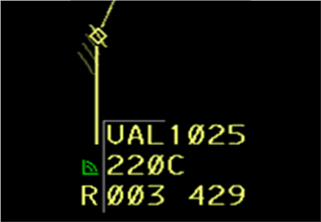
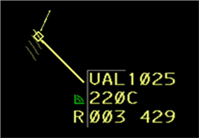
FDBs can be offset to any of eight compass directions. The direction of the leader line will correspond to the number’s position on the keypad, i.e. 7 NW, 8 N, 9 NE, etc.
{direction} <SPACE> {FLID} <KBE>
The controller can adjust the DB offset and leader line length for individual FDBs in a Single Entry by typing a number to indicate the direction, a /, the number to indicate the length, a space, FLID, and ENTER.
{direction} / {length 0-3} <SPACE> {FLID} <KBE>
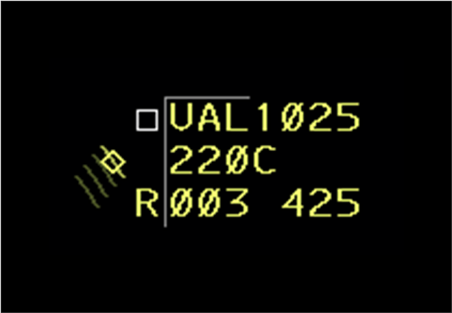
The system attaches the leader line to the data block at different points depending on the offset position selected. The attachment points will also vary when the user selects a zero leader length. The system varies the length of (truncates) the leader line when there are overlying symbols or characters. This is done to maintain the data block position in reference to the target symbol and prevents data block “jump”.
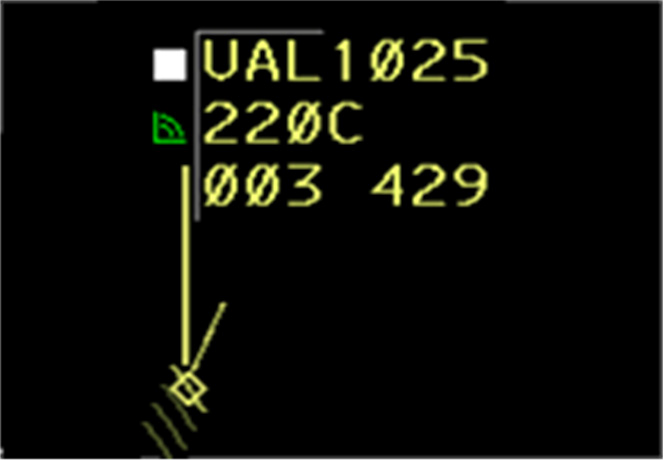
The following depicts FDB position offsets without truncation. Truncation is not currently implemented.
7 / NW
8 / N
9 / NE
4 / W
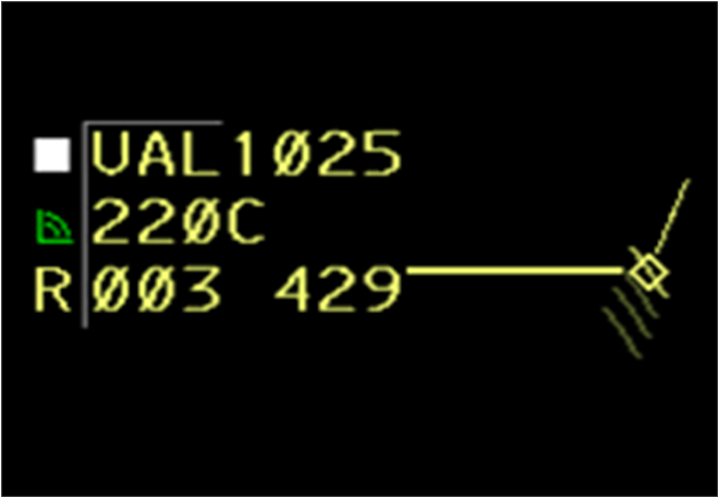
6 / E
1 / SW
2 / S
3 / SE
/0 - West
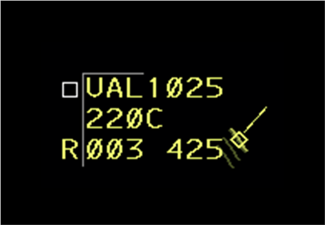
/0 - East
The LDB can be displayed as paired or unpaired. Paired and unpaired LDBs may be displayed to the left or right of the target symbol location. LDBs have no track position symbol, leader line, or velocity vector.
- Displays ACID and Mode C altitude.
- NO position symbol, leader line, or velocity vector.
- Displayed at LDB brightness.
Not implemented yet.